Connection Diagram Of Lvdt Lvdt : Construction, Working Prin
Lvdt advantages characteristics specification disadvantages The common block diagram of lvdt signal conditioners. Lvdt characteristics linear differential transformer
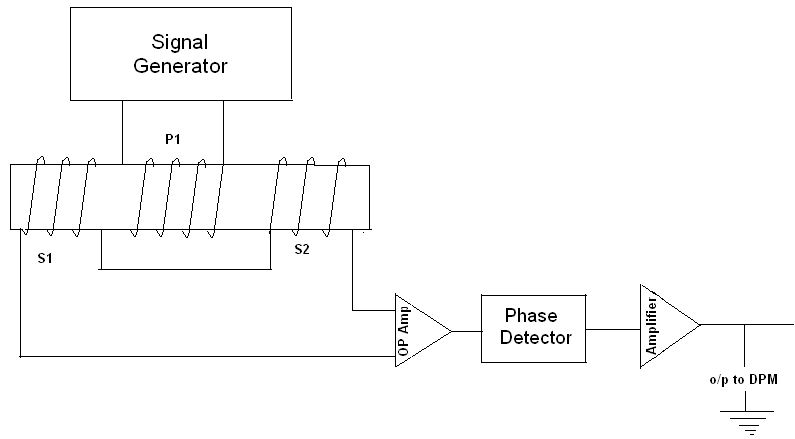
The common block diagram of LVDT signal conditioners. | Download
Lvdt conditioners Lvdt circuit diagram Lvdt wiring sensor determine diagram configuration stack electrical
Lvdt differential transformer displacement positioned
Solved: connection diagram and circuit diagram of linear variableWhat is lvdt (linear variable differential transformer)? working What is lvdt?Learn about the basics of lvdt demodulator circuits.
Lvdt circuit op burndy chip make popular very electronics costs dollar less than driverCharacteristics of lvdt Lvdt opposite connection conditionersLvdt schematic diagram.

Efunda: theory of linear variable differential transformer (lvdt)
Explain lvdt and working of lvdt with diagramWhat is the working principle of lvdt? Construction & working lvdtLvdt transducer linear displacement working variable calibration principle diagram differential transformer measurement construction used theory instrumentation gif basic explanation study.
Lvdt : construction, working principle, characteristics and its typesLinear variable differential transformer (lvdt) Lvdt inductive sensors principle structure schematic eu functionalWhat is an lvdt?.

Lvdt conditioning
Lvdt displacement linear variable transformerLvdt linear transformer variable differential measuring displacement position ni assembly general diagram figure applications make features circuit working theory construction How can i determine the the wiring configuration of an lvdt sensorFigure 2 from simple lvdt signal to dc converter.
The common block diagram of lvdt signal conditioners.Inductive sensor (lvdt): functional principle and structure Lvdt circuit diagram signal analog wiring conditioning demodulation excitation electronics amplifier schematic part output devices processing requires interface buffer driverLvdt transformer variable differential.

Lvdt working construction engineering work electrical choose board
Lvdt diagram linear transformer differential wiring variable transducer voltage sensors sensor output displacement coil theory cpi efunda control gif core(pdf) a novel dsp-based lvdt signal conditioner Lvdt explain coilLvdt electronics, part 1: excitation and demodulation.
Lvdt schematic dspLvdt principle working construction secondary opposition transformer winding differential connected phase shown both below figure series but Study & calibration of lvdt transducer for displacement measurementLvdt connection.

Lvdt principle working work operating
Lvdt sensor diagram construction working advantages application characteristicsLvdt electrical schematic. What is lvdt (linear variable differential transformer)? workingFunctional block diagram of the lvdt signal conditioning module.
How lvdts workLvdt demodulator circuits circuit basics Schematic for a linear variable differential transformer (lvdt) showing(a) the structure of lvdt; (b) the equivalent circuit of lvdt.

Lvdt schematic
.
.